Three Accepted Verification Methods in ISO/IEC 80079‑34:2020 – My Practical Interpretation
Disclaimer:
The interpretations provided herein are based solely on my personal experience in electronics manufacturing and ATEX-related processes. They do not constitute official guidance and must not be applied in practice without proper consultation. Compliance with ISO/IEC 80079-34:2020 must always be ensured in coordination with the relevant national ATEX certification body. The manufacturer and their notified body retain full responsibility for conformity—this text does not replace that obligation.
Over the course of my long career in electronics manufacturing, I’ve encountered various interpretations of how ATEX requirements are implemented on production lines. One of the more practical parts of the ISO/IEC 80079‑34:2020 standard is section A.4.2.2, which outlines how safety-critical components must be verified on populated PCBs.
The standard accepts three methods—A, B and C—for this verification. Below, I’ll walk through each method and provide my personal interpretation of how these requirements can be met in real-world production environments.
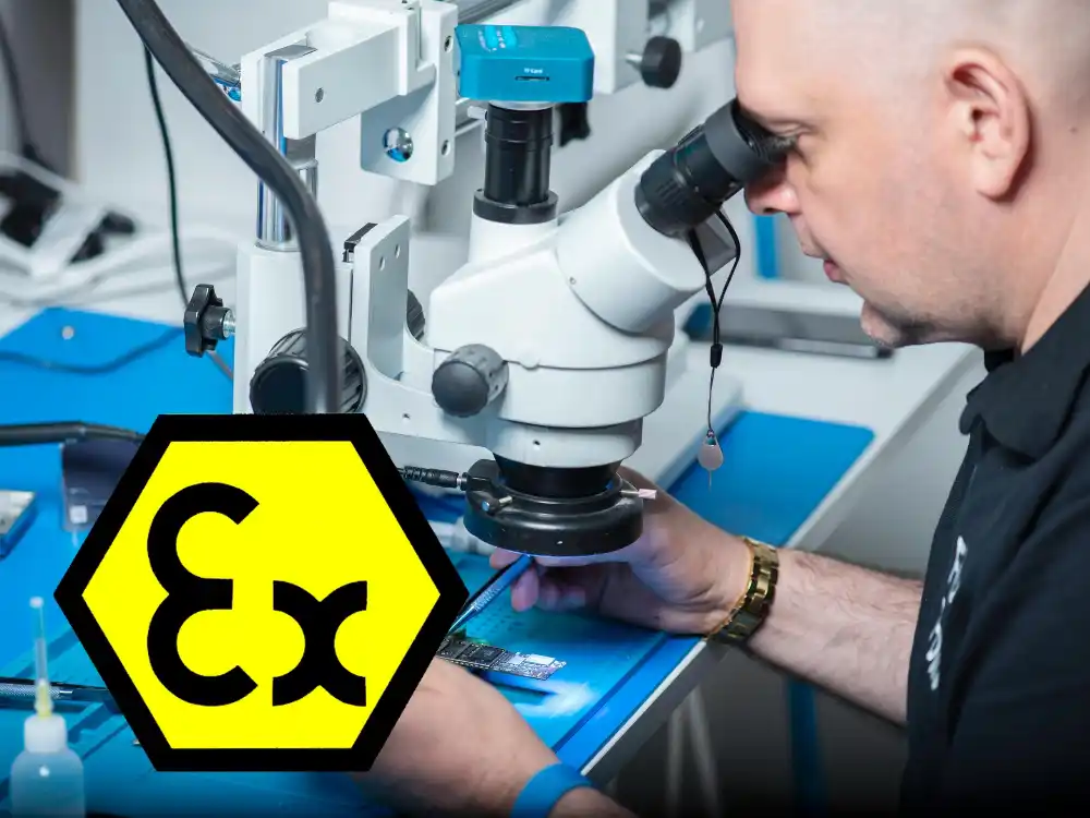
Method A: Visual Verification
Standard requirement: Every ATEX-critical component must be visually verified on the finished PCB.
In practice, this means:
- Ensuring the component is exactly as defined in the Ex certification—correct type, value and manufacturer.
- Confirming correct polarity (e.g., diode is not reversed).
- Checking that the component’s orientation and position are correct.
When I use this method:
Ideal for small production batches, prototyping or when components are placed by hand. The inspector must be trained, and visual aids like magnifying glasses or microscopes are often necessary.
My interpretation:
Although this is the most direct and officially accepted method, it is also the most burdensome for the operator and, in my view, the least reliable in practice. Human visual inspection is never error-free, especially when verifying microscopically small component markings. In fact, the typical accuracy of manual visual inspection in electronics manufacturing ranges from 55% to 75%, depending on the conditions and complexity. The cognitive load, eye strain, and risk of oversight make this method unsuitable for any environment where consistent and repeatable quality is required. While it may technically fulfill the standard, it often fails to provide the process reliability expected from ATEX-level compliance.
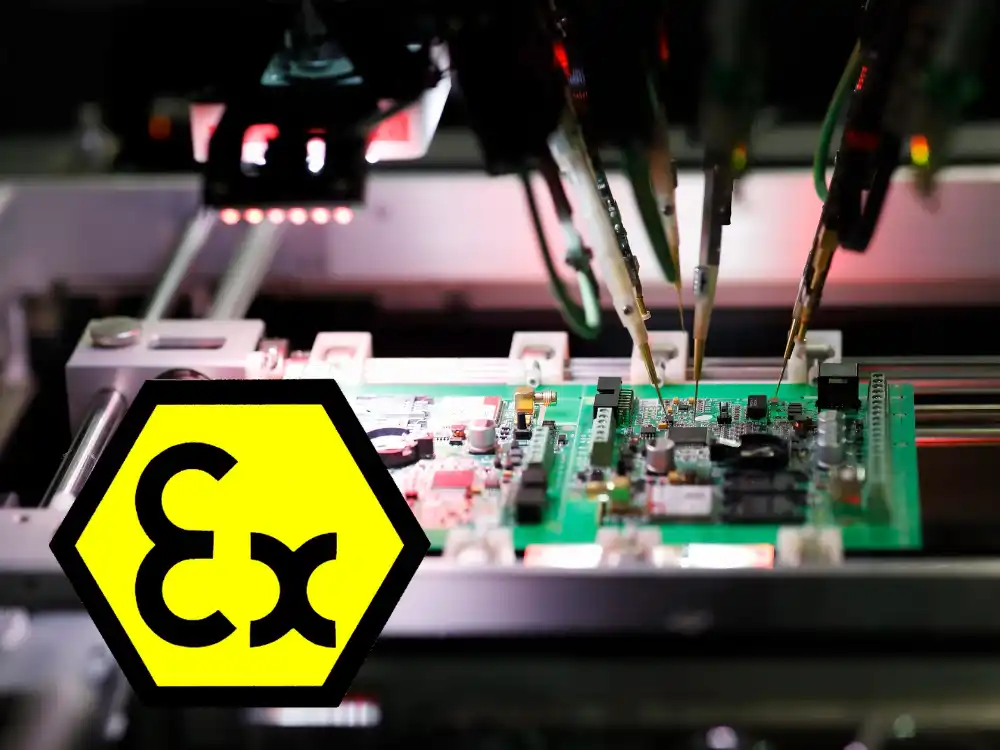
Method B: Feeder Setup + Visual Placement Check
Standard requirement: The correct loading of component reels into the pick-and-place machine must be verified, followed by visual inspection of each ATEX-critical component’s placement and orientation.
In practice, this means:
- Component reels are loaded into the machine, verified either by barcode or by cross-checking setup lists.
- After SMT placement, the following are visually inspected on the PCB:
- Component orientation and placement are correct, meaning the component is aligned properly and fully seated on its pads with no overhang.
- Polarity is correct.
When I use this method:
Best suited for high-volume SMT production, but can also be used effectively in smaller series with proper process discipline.
My interpretation:
In my experience, this method can be virtually error-free, even when the feeder setup and verification process are performed manually. If the setup procedures are followed precisely and documented properly, and the machine places components as programmed, the component identity and placement are both assured. Visual verification of orientation is a straightforward step that reinforces process integrity. Moreover, this step can also be performed using Automated Optical Inspection (AOI) systems, which provide efficient and highly reliable visual checks without the typical risks associated with human inspection. When implemented with discipline, this method offers an excellent balance of reliability and scalability for ATEX-critical assemblies.

Method C: Automatic Test Equipment (ATE) + Visual Check for Certain Components
Standard requirement: All ATEX-critical components must be verified by automated testing, and type numbers of parallel Zener or diode assemblies must be visually checked.
In practice, this means:
- A test system (e.g., flying probe) verifies the presence and electrical behavior of each ATEX-critical component.
- For parallel-connected Zener diodes or diode groups, component markings must be visually checked to confirm type.
When I use this method:
Practical when the production line has ATE capabilities and the board has only a few testable ATEX-critical components.
My interpretation:
This is an efficient option for lines equipped with test infrastructure. However, it does not eliminate the need for visual verification in all cases—especially for parallel-connected components. As such, ATE should be seen as complementary to visual checks, not a replacement.
Summary Table
| Method | What’s Verified | When to Use | My Notes |
|---|---|---|---|
| A – Visual | Human checks each component | Small batches, manual assembly | Burdensome, 30–40% error rate |
| B – Feeder + Visual | Feeder setup verified, placement checked | SMT production, manual or automated | High reliability; AOI systems further enhance accuracy |
| C – ATE + Visual | Test system + visual type check | Few testable Ex-critical parts | Fast, but not fully visual-free |
Clarifying “Manually Assembled” in the Context of Clearance Verification
Section A.4.2.2 of the ISO/IEC 80079‑34:2020 standard includes the requirement:
Specified distances and clearances on manually assembled PCBs should be verified on a 100 % basis.
It is important to understand what “manually assembled” means in this context. This requirement does not apply to components placed using automated machinery such as SMT lines. Instead, it is strictly limited to boards where the component placement is performed by hand. In practical terms, “manually assembled” means:
- Surface-mount components have been placed manually and then soldered either with a soldering iron or in a reflow oven.
- Through-hole components have been inserted manually and soldered with a soldering iron or in a wave soldering machine.
- Any process where a person determines the final position of a component on the PCB by manually placing it.
In such cases, the installer’s actions directly affect the final spacing between components, pads, or tracks. Therefore, the standard requires that the defined clearance distances are verified 100% to ensure compliance with safety-critical design rules. For automated processes, such as machine placement with controlled coordinates and tolerances, this particular clearance verification rule does not apply.