Haaste manuaaliselle tarkastukselle: Quins-tarkastusjärjestelmä
Jokainen, joka on työskennellyt automaattisten optisten tarkastusjärjestelmien (AOI) kanssa, tuntee varmasti haasteet. Etenkin pienten tuotantosarjojen ja nopeasti muuttuvien vaatimusten kohdalla. Perinteiset AOI-järjestelmät vaativat usein huomattavan paljon aikaa ohjelmointiin ja virheenkorjaukseen. Tämä aika voi helposti syödä järjestelmän hyödyt, jolloin käyttö pienissä tuotannoissa on hidasta ja kallista. Tällöin manuaalinen tarkastus osoittautuu usein tehokkaammaksi ja kustannustehokkaammaksi vaihtoehdoksi. Keskikokoiset ja suuret tuotantosarjat ovat toki sitten eri juttu.
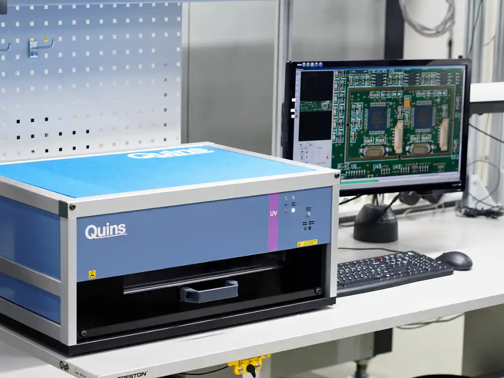
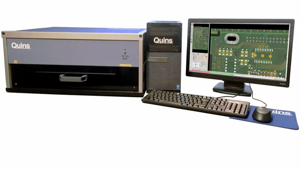
Quins avustava tarkastusjärjestelmä tarjoaa innovatiivisen vaihtoehdon manuaaliselle mikroskoopin alla tapahtuvalle tarkastukselle Tämä ohjelmistopohjainen optinen tarkastusjärjestelmä poistaa tarpeen AOI-laitteista tutulle raskaalle ohjelmoinnille. Sen sijaan se käyttää yksinkertaista ja intuitiivista lähestymistapaa: piirilevystä otetaan referenssikuva, ja tarkastettavia piirikortteja verrataan siihen. Järjestelmä näyttää referenssikuvan ja tarkastettavan piirikortin kuvia nopeassa tahdissa ruudulla, mikä tekee poikkeamien havaitsemisesta helppoa käyttäjälle.
Miten se toimii?
Käyttäjä skannaa referenssikuvan järjestelmään, joka jakaa tarkastettavan levyn pienempiin, helposti tarkistettaviin sektoreihin. Näiden sektoreiden kokoa voi tarvittaessa säätää. Tarkastus etenee järjestelmällisesti, sektori sektorilta, varmistaen, ettei yksikään alue jää huomaamatta. Tämä on selkeä parannus manuaalisiin mikroskooppitarkastuksiin verrattuna, joissa satunnaiset alueet piirikortilta voivat jäädä kokonaan tarkastamatta.
Quins ei käytä automaatiota poikkeamien havaitsemiseen, vaan se antaa käyttäjälle mahdollisuuden tunnistaa erot näytöllä. Poikkeamat on visuaalisesti helppo havaita kuvien vuorottelun ansiosta. Quins vaihtaa nopeasti referenssikuvan ja tarkastettavan kuvan välillä, jolloin kaikki poikkeamat hyppäävät selkeästi käyttäjän silmille. Yllättävää kyllä, tämä manuaalisen kaltainen lähestymistapa on erittäin tehokas, ja koska aikaa vievää ohjelmointia ei tarvita, järjestelmä on nopea ottaa käyttöön. Refernssikuvan skannaamiseen ei tarvita erityisiä taitoja.
Helppoa vianetsintää
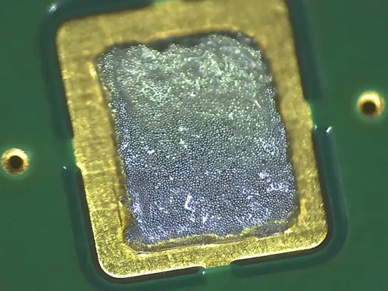
Quins ei ole pelkästään erinomainen työkalu laadunvalvontaan tuotannon aikana, vaan se on myös tehokas apuväline vianetsinnässä. Jos piirilevy ei toimi sähköisessä testissä, Quinsin avulla on helppo tunnistaa mahdolliset ongelmat, kuten puuttuvat komponentit, väärät polariteetit, tinasiltoja tai muita kokoonpanovirheitä. Vertaamalla viallista levyä referenssikuvaan käyttäjät voivat paikantaa viat nopeasti ja tehokkaasti, mikä säästää aikaa korjausprosessissa.
Tarkastusten ja korjausten täydellinen jäljitettävyys
Yksi Quins-järjestelmän erinomaisista ominaisuuksista on sen kyky dokumentoida kaikki tarkastus-, vika- ja korjaustiedot. Jokainen havaittu ongelma kirjataan automaattisesti tietokantaan, sisältäen tiedot kuten komponenttitunnisteet, vikatyyppejä ja visuaalisia todisteita. Quins Statistics -moduuli mahdollistaa näiden tietojen analysoinnin trendien ja suorituskyvyn osalta, kun taas Quins Repair -moduuli varmistaa, että jokainen korjaus- tai hylkäyspäätös on jäljitettävissä. Kun piirikortit sarjanumeroidaan, koko prosessi tarkastuksesta korjaukseen on täysin dokumentoitu, täyttäen tiukat jäljitettävyysvaatimukset esimerkiksi lääke-, ilmailu- ja puolustusteollisuudessa.
Täytyy huomoida, että statistiikka- ja korjaustietojen täysi hyödyntäminen edellyttää referenssikuvan lisäksi myös komponenttien paikkatietojen tuomista järjestelmään.
Miksi valita Quins vuonna 2024?
Seitsemän vuoden aikana, jotka ovat kuluneet tämän artikkelin alkuperäisestä julkaisusta, joustavien ja edullisten tarkastusratkaisujen kysyntä ei ole kadonnut. Intuitiivisen käyttöliittymänsä, kattavien ominaisuuksiensa ja mukautuvuudestaan eri tuotantotarpeisiin Quins on edelleen houkutteleva valinta elektroniikan valmistajille, jotka pyrkivät kuromaan umpeen manuaalisten ja täysin automatisoitujen tarkastusten välistä kuilua.
Lisätietoja järjestelmästä löydät valmistajan nettisivuilta: www.quins.de.