The Importance of Soldering Temperature: Finding the Right Balance
Soldering is a fundamental process in electronics manufacturing and repair, but one of the most crucial factors determining the success of a solder joint is temperature. Setting the correct soldering iron temperature ensures a strong, reliable connection while minimizing the risk of damage to components and PCBs.
Understanding Soldering Temperature
The ideal soldering temperature depends on several factors, including the type of solder alloy, component sensitivity, and the thermal mass of the solder joint. A well-calibrated soldering station allows for precise adjustments, optimizing both efficiency and quality.
Recommended Temperature Ranges
| Application | Temperature Range (°C/°F) |
|---|---|
| General-purpose soldering (FR4/Glass fiber) | 320–380°C (608–716°F) |
| General-purpose soldering (Ceramic) | 400-450°C (752–842°F) |
| Large ground planes | 370–420°C (698–788°F) |
Why Soldering Temperature Matters
- Proper Solder Wetting – Solder must flow smoothly onto both the component lead and PCB pad to form a strong bond. If the temperature is too low, the solder will not wet properly, leading to weak or cold joints.
- Minimizing Thermal Stress – Excessive heat can damage sensitive components, lift PCB traces, and degrade insulation on wires. A precise temperature ensures components reach soldering temperature without excessive exposure.
- Avoiding Oxidation and Tip Wear – High temperatures accelerate oxidation on both the soldering tip and the solder itself, reducing the lifespan of equipment and increasing the need for cleaning.
- Efficient Heat Transfer – The right temperature, combined with an appropriate soldering tip, ensures efficient heat transfer, reducing the time required to complete a joint and minimizing overall thermal impact.
Finding the Optimal Soldering Temperature
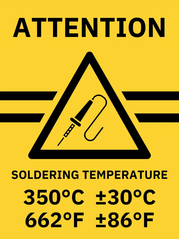
A practical approach is to start at 350°C (662°F) and adjust as needed. Fine-tuning ±30°C (±86°F) depending on the job helps accommodate factors like:
- The type of solder alloy used (lead-based vs. lead-free)
- The size and thermal mass of the joint
- The type of soldering tip being used
- The PCB material (FR4, ceramic, etc.)
- The presence of heat-sensitive components
If the PCB material is something other than FR4/glass fiber, adjusting the soldering temperature may be necessary. For example, ceramic PCB boards often require higher soldering temperatures (400–450°C / 752–842°F). However, if heat-sensitive components are involved, it may be necessary to lower the temperature to 350°C (662°F) or below to avoid component damage.
If combining ceramic or FR4/glass fiber PCB boards with large ground planes and heat-sensitive components, careful temperature management is essential to avoid soldering issues or component damage.
A larger soldering tip allows for better heat transfer, often reducing the need for higher temperatures. On the other hand, fine or pointed tips may require slightly increased temperatures to compensate for heat loss.
Common Mistakes in Soldering Temperature Selection
❌ Too High (>400°C / >752°F): Burns flux too quickly, causes PCB damage, and oxidizes the tip rapidly.
❌ Too Low (<300°C / <572°F): Leads to poor wetting, cold joints, and excessive dwell time, which can stress components.
❌ Ignoring Thermal Mass: Large components or ground planes require more heat, while fine SMD parts need controlled, lower temperatures.
Conclusion
Mastering soldering temperature is key to producing reliable, durable solder joints. By understanding temperature requirements and making fine adjustments based on the specific application, electronics professionals and hobbyists can enhance their soldering efficiency while ensuring long-lasting connections.